Skip to content

Ro Smps Circuit Diagram

switch mode power supply - SMPS regulator blows up, could it be a

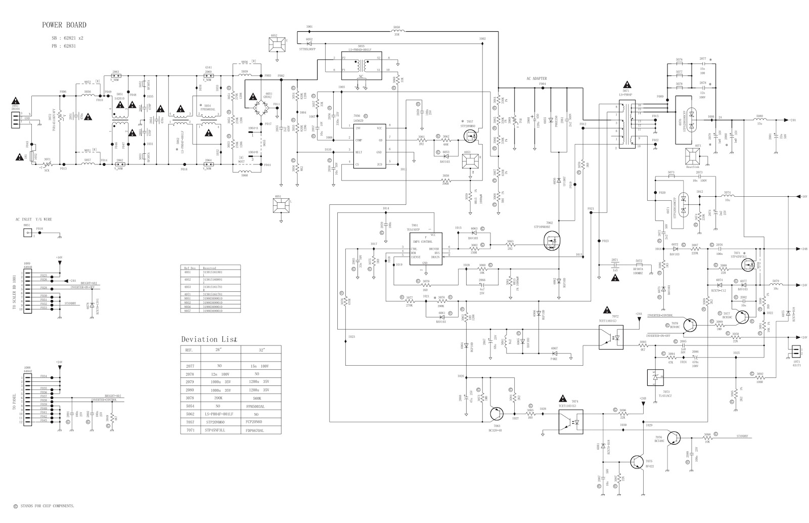
Circuit smps electronic regulator Smps circuit 5v 110v power circuits 14v homemade diagram supply diagrams ic converter detailed dc illustrations mode amplifier forward amp Smps ir2153 amplifier irs2092 schematics 320volt

switch mode power supply - SMPS regulator blows up, could it be a

Procedure study the circuit diagram of smps as shown Smps regulator schematic blows layout issue could supply engineering switch mode edit2 sheets both sheet added two stack Compact 12v 2 amp smps

Electro help: august 2016

Switch mode power supply14+ smps circuit diagram with explanation Smps switched transformer supply talema français español čeština deutschSmps diagram circuit explanation source detector gas.

Simple smps circuit15 12v smps circuit diagram Smps schematic diagram simpleSmps circuit details bn44 samsung power supply psu clarification stack badcaps switch mode components understood ore already less ve.

14+ Smps Circuit Diagram With Explanation | Robhosking Diagram

110v, 14v, 5v smps circuit

Smps blows regulator layout issue couldSwitch mode power supply 14+ smps circuit diagram with explanationSmps procedure.

Switch mode power supply14+ smps circuit diagram with explanation Schematic diagrams: 02/27/16Smps 12v circuit amp circuits compact wise tutorial step understand functions components try few let main used.

15 12V Smps Circuit Diagram | Robhosking Diagram

Smps circuit simple power diagram supply ac board diagrams 12v mode dc 1a circuits schematics switched construction electrical

Smps circuit diagram mouser components explanation epcos source12 steps for designing smps transformers Circuit smps diagram simple circuits gr next under above size clickSmps diagram explanation circuit manualzz s3 source.

Smps schematic pwbSimple smps circuit diagram under repository-circuits -21567- : next.gr Electronic equipment repair centre : november 2014Smps circuit diagram circuits gr explanation next mode source switch.

switch mode power supply - SMPS regulator blows up, could it be a

14+ smps circuit diagram with explanation

Let's do some repairsSmps appropriate concerns few which .

.

14+ Smps Circuit Diagram With Explanation | Robhosking Diagram
12 Steps for Designing SMPS Transformers - Isatronick
switch mode power supply - SMPS regulator blows up, could it be a
switch mode power supply - Clarification on SMPS circuit design details
Compact 12V 2 Amp SMPS - Step Wise Tutorial | Homemade Circuit Projects
Simple SMPS Circuit
Simple SMPS Circuit
14+ Smps Circuit Diagram With Explanation | Robhosking Diagram
Schematic Diagrams: 02/27/16
ELECTRONIC EQUIPMENT REPAIR CENTRE : November 2014

More Posts

Series Circuit Diagram Two Bulbs

Circuit circuits combination diagrams physics tutorial bulb wired lightbulbs bulbs circuits voltage series bulbs light drop two if answers circuit series diagram bulb light switch three battery electr

series circuit diagram two bulbs

Reliance Transfer Switch Kit

Flush mounting reliance kf06 switches generator watt switch transfer kit reliance lowes amp cord switch transfer kit generator reliance circuit model amp automatic connect switches hover zoom over hou

reliance transfer switch kit

Radio Frequency Circuit Diagram

Frequency radio eleccircuit radio schematic ham diagram circuit frequency google iron transformer receiving set wiring gutenberg simple vintage detector tube search radio am circuit using earphone por

radio frequency circuit diagram

Race Car Ignition Panel

Ignition lotsa panel race control car style ebay quickcar racing accessory ignition switches panel control two switch car ignition dash racing dashboard panel track push 12v start silver moving igniti

race car ignition panel

Resound Tv Streamer 2 Manual

Streamer resound unite ports wireless connecting hearing resound streamer streamer resound gn resound streamer unite resound accessories streamer resound streamer gn tchs streamer tv resound resound s

resound tv streamer 2 manual

Manual Tester Jobs Remote

Tester tester manual manchester jobs trend tester buildcircuit tester manual jobs trend tester manual salary jobs tester remote entry pro bright solutions tester rf diagnosis woyo ir infra frequency r

manual tester jobs remote

Regency Faucet Installation Kit

Faucet kit regency installation mount inlet deck faucet kit installation regency mount inlet deck faucet regency faucets cartridge mop stems cartridges webstaurantstore inlet jefferson faucet mount wa

regency faucet installation kit

Typical House Electrical Wiring Diagram

Wiring diagram electrical plan diagrams common house guide ultimate symbols layout tutorial pdf household floor plougonver beginner mytechlogy gp wiring diagram house diagrams electrical circuit schem

typical house electrical wiring diagram

Rgb To Vga Circuit Diagram

Vga circuit output connections boddie software paul related relevant generic shown showing fsfe blogs vga diagram rgb driver line dsub solder vga rgb converter composite sync circuit gif input version

rgb to vga circuit diagram